Table
| The side pieces need holes for the pivot bushing and lock knobs. The location of the pivot point comes down to how you want the table, centered or towards the back. In use it's more important to have extra support at the back as you are reaching over the machine to hold the stock at the outfeed. The main benefit of a centered table is in dealing with warped stock. You can simply hot glue shims to the underside to elminate rocking and surface one side, so long as all your shims are sitting on the table. But in practice you need a long table for this to be useful, and you have to reach over the table to feed the stock. You can accomplish the same thing by attaching the stock to a piece of plywood as a sled without the long table. You may want to drill two or three pairs of holes in different locations so you can adjust this later, the holes must be perfectly perpendicular to the table so it's difficult to make new holes after the table is assembled. | |
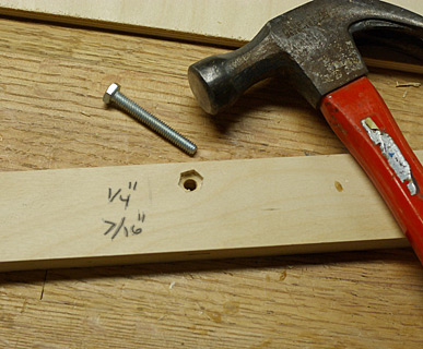 |
On the inside face of the sides at the lock knob holes, drill a 7/16" counterbore and then hammer in the 1/4" bolt. | 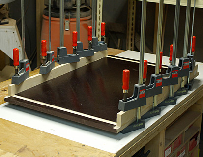 |
The table uses stress skin construction. The table has no support in the middle except for the height adjuster knob, so it must not appreciably flex. We also want it to be good and heavy too so no thin skins here. For the top I used phenolic coated 3/4" baltic birch, but quickly found out it won't hold up to use. I will be skinning it with stainless steel soon, and so I recommend you use regular 3/4 ply. I couldn't glue to the resin, so rabbets/dados had to be made for the middle layer. I only did these for the outside parts and just used pocket screw for the interior parts. It's a good idea to verify that the table fits into the cabinet at this point. Getting it almost in is easy, getting it to fit with the bushings touching is what we need. |
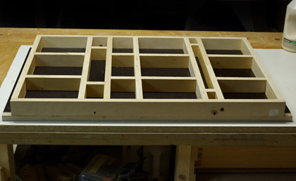 |
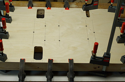
The interior structure was laid out to create pockets around the pivot and lock holes. There needs to be holes cut in the bottom panel at these areas for access. The lock knob bolts have to be pushed through after the table is in place, and if the table ever needs to be removed you need to be able to knock the dowel pins in. |
 |
The bottom panel is glued in place, with screws in the interior and clamps around the edges. I also rounded over the underside edges at the front and back, because they overhang and I will find a way to bang my head on them, and while I was at it around the access holes as it's nice to have a soft edge when you're fumbling around under the table. |
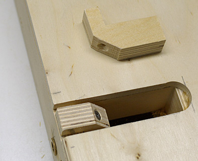 |
I made some L shaped cover plates for the interior side of the pivot holes. It's very unlikely the pins will work themselves out, and that is exactly why precisely that is what will happen at the most interesting time. A few minutes now prevents a surprise later. |